Reading an electrical drawing is a key skill. The ability to quickly identify a transformer symbol is fundamental to that skill, since transformers step voltage up or down, provide isolation, and serve as a cornerstone of power systems and electronics.
The most common transformer symbol consists of two coils separated by a core. It looks like this: (~~~ || ~~~).
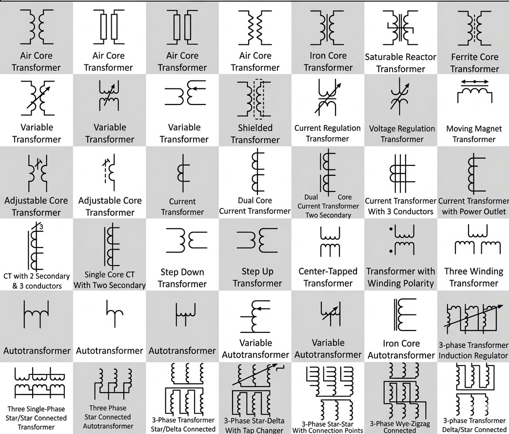
This guide will break down every common transformer circuit symbol you’ll encounter in schematics. We will equip you to read any schematic with confidence, understanding not just the symbol, but its function within the circuit.
To master the symbols, we first must understand why they exist. They are more than just pictures; they are a shared language that engineers and technicians use every day.
Electrical schematics are the universal language for engineers, technicians, and electricians. They provide clarity and help prevent costly errors.
Like letters forming words, these standard symbols form circuits. Anyone trained in the language can pick up a schematic and read it right away.
A transformer works on the principle of mutual inductance, where a changing magnetic field in one coil induces a voltage in another. The symbol must show this core function quickly, without needing paragraphs of text.
It tells you how energy moves and changes in the circuit.
Every part of a transformer symbol has a specific meaning. By breaking down the symbol, we can learn to read its visual grammar.
The coiled lines (~~~) represent the windings. The primary winding is the input side, and the secondary winding is the output side.
The number of loops drawn is purely symbolic, not a literal count. However, the ratio of windings determines whether the transformer is step-up or step-down.
The lines drawn between the windings represent the transformer’s core, which carries the magnetic field. The type of line tells you about the core material and its use.
| Core Symbol | Core Material | Common Application |
|---|---|---|
||
|
Iron Core | Low-frequency, high-power (e.g., power distribution) |
- -
|
Ferrite Core | High-frequency (e.g., switch-mode power supplies) |
| (No Lines)
|
Air Core | Very high-frequency, RF circuits (e.g., radio tuners) |
Small dots placed at the end of each winding are polarity marks. This is known as the dot convention, and it matters a lot for circuits where phase relationships are important.
The rule is simple: when current enters the primary winding’s dot, the induced current exits the secondary winding’s dot. This means the dotted ends are in phase with each other.
Here is a quick-reference guide to the most common transformer symbols you will encounter in schematics.
| Symbol (Glyph) | Name & Keywords | Common Application |
|---|---|---|
(~~~ || ~~~) |
Single-Phase Transformer | General-purpose, residential power, consumer electronics. |
(Y - Δ) |
Three-Phase Transformer | Industrial motors, power distribution grids. |
(~~ tap ~) |
Autotransformer | Voltage regulation, starting large motors. |
(~~~ || tap ~~~) |
Center-Tapped Transformer | Dual-voltage power supplies (e.g., +12V / -12V). |
(conductor through O) |
Current Transformer (CT) | Safely measuring high AC currents for metering and protection. |
(~~~ || ~~~) |
Potential Transformer (PT/VT) | Safely measuring high AC voltages for metering. |
This is the most basic electrical transformer symbol. It shows up everywhere, from phone chargers to residential power step-down applications.
Three-phase power is the backbone of the world’s electrical grids, and its symbols show the winding setups, such as Delta (Δ) and Wye (Y or Star). Reading these symbols is a must for anyone working with industrial machines.
This transformer uses a single tapped winding for both its primary and secondary sides. It is not meant for isolation, but it works very well for small voltage adjustments.
This function is often implied by the circuit’s context rather than shown by a unique symbol. A schematic for a low-voltage device connected to mains power implicitly uses a step-down transformer.
A tap on the secondary winding adds an extra connection point, which splits the output voltage in two. This is essential for creating bipolar DC power supplies from a single AC source.
Current Transformers (CT) and Potential Transformers (PT) are used to safely measure high currents and voltages, stepping these values down to a safe level for meters and relays.
Knowing the symbols is one thing, but reading them inside a live circuit is another. Here, we will show you how these symbols work in a real-world design.
Imagine a simple AC-to-DC power supply schematic. It shows an AC source, a transformer circuit symbol, a bridge rectifier, a smoothing capacitor, and a load resistor.
While symbols are largely standard, you may run into slight differences depending on the region or the age of the diagram. These small changes are easy to handle once you know what to look for.
Minor regional differences exist, mainly between IEC (International Electrotechnical Commission) and ANSI (American National Standards Institute) standards. For transformers, the symbols look very similar, but it is good to know about standards like IEC 60617.
The IEC transformer symbol works the same as the ANSI coil-based symbol. It may just appear with cleaner lines in some CAD software.
A variable transformer, or Variac, is shown with an arrow passing through the windings, which means the output voltage can be adjusted. These are common on lab benches and in test equipment where precise voltage control is needed.
Understanding transformer symbols is the first step toward fluency in the language of electrical engineering. We have covered the anatomy of a symbol, from its windings and core to its polarity marks.
We also provided a glossary of common types and walked through a practical schematic example. With this knowledge, you can confidently read, design, and troubleshoot circuits.
Now that you can read electrical transformer symbols with ease, the next step is picking the right hardware for your project. When you are ready to bring your schematic to life, browsing a professional catalog of high-quality transformers helps you match the right part to your design.
 Products
 Projects
 Solutions
 Service
 News
News About CNC
 Contact Us

