Both autotransformers and isolation transformers perform voltage conversion. The key difference is in how they are built and what they do.
The single most important distinction is this: autotransformers use a single, shared winding, while isolation transformers use two physically and electrically separate windings. This structural difference shapes everything else about them.
This includes safety, size, cost, and which applications each type fits best. This guide breaks down each type clearly, compares them side by side, and gives you a simple framework for making the right choice.
An autotransformer is small, efficient, and affordable. However, these strengths come with a real safety trade-off.
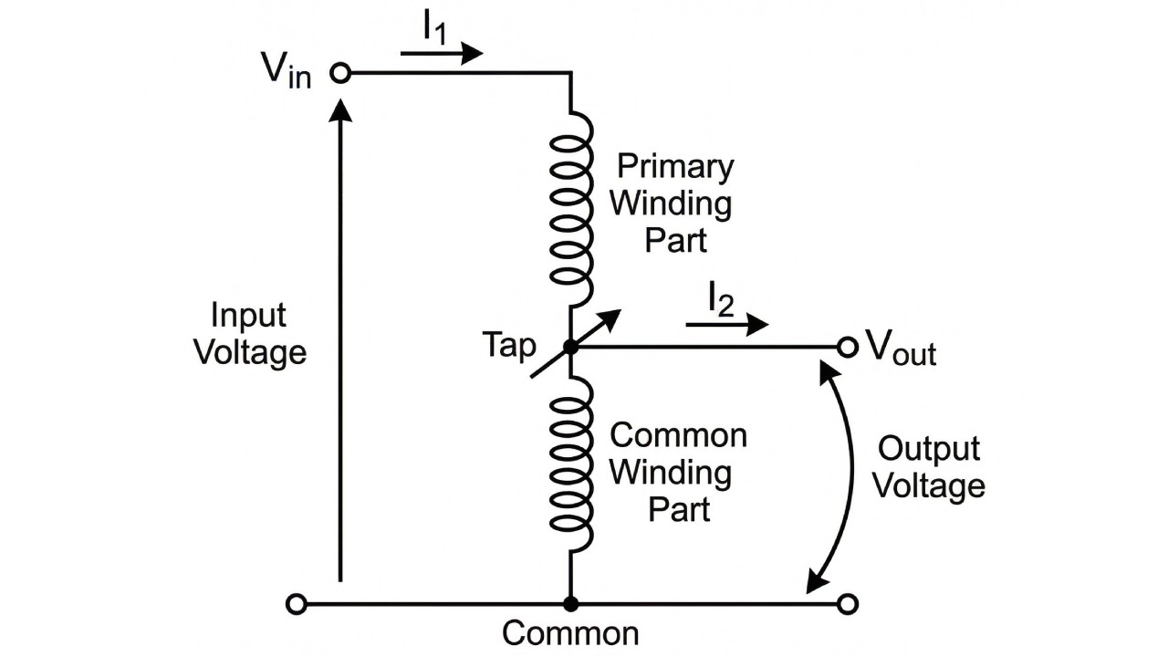
An autotransformer has only one winding. A portion of that winding is shared between the input and output circuits, and a tap along the winding sets the output voltage.
Power moves through two paths: electrical conduction through the shared part and magnetic induction through the whole winding. This dual method is what makes the design work.
According to the operating principle of autotransformers, this shared-winding design is what makes them smaller, lighter, and cheaper than two-winding transformers.
An isolation transformer puts safety first. It uses physical separation between windings to create full electrical independence.
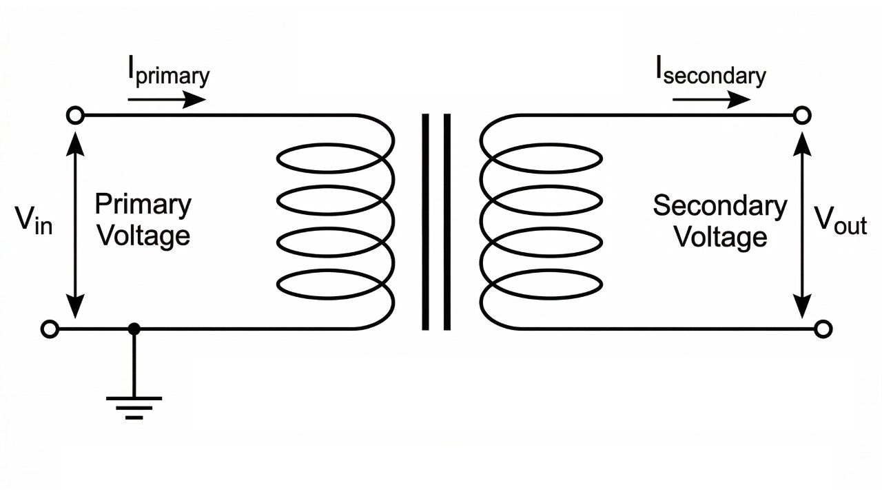
This transformer has two separate windings: a primary and a secondary. They share no electrical connection.
The windings are linked through a shared iron core using magnetic fields. All power transfer happens through magnetic induction alone.
This complete electrical separation is called galvanic isolation, a topic frequently covered in discussions among electrical professionals. It is the defining feature of this transformer type.
This table gives a clear, side-by-side summary of the key differences between the two transformer types.
| Feature | Autotransformer | Isolation Transformer |
|---|---|---|
| Winding Construction | Single, tapped winding | Two or more separate, isolated windings |
| Power Transfer Method | Conduction and Induction | Purely Induction (Magnetic) |
| Galvanic Isolation | No | Yes |
| Safety | Lower; fault can expose output to full input voltage | Higher; physical separation prevents direct fault transfer |
| Size & Weight | Smaller and lighter for the same kVA rating | Larger and heavier for the same kVA rating |
| Cost | Lower | Higher |
| Efficiency | Higher (typically 98-99%) | Lower (typically 95-98%) |
| Typical Applications | Voltage regulation, motor starting, grid inter-ties | Medical equipment, test benches, sensitive electronics |
With this clear comparison, you can start to see which transformer fits your project best. If you are ready to look at specific models, viewing a full range of options can be a helpful next step. Explore our full range of high-quality transformers at the CNC Power transformer product page.
Features a fully oil-filled, sealed corrugated tank that naturally adapts to oil expansion. Engineered for high efficiency and low loss to significantly save power consumption and operating costs.

To choose correctly, go beyond a simple pro/con list. Ask these key questions about your specific application.
Looking at real-world examples helps confirm which transformer fits your needs.
For heavy industrial tasks like motor starting, a strong and reliable autotransformer is essential. When picking one, consider its power rating and tap options carefully.
A common point of confusion is the link between buck-boost transformers and autotransformers. A buck-boost transformer is a small isolation transformer built for minor voltage changes, usually in the plus or minus 10 to 20 percent range.
However, to work most efficiently, it is almost always wired as an autotransformer. As detailed in buck-boost transformer design guides, the primary and secondary windings are connected in series with the load.
This connection either adds to or subtracts from the source voltage. It is a powerful and cost-effective fix for voltage correction when full isolation is not needed.
Quickly calculate the final load voltage when using a buck-boost transformer to compensate for line voltage drop or overvoltage.
Final Load Voltage (Vload):0 V
The importance of galvanic isolation cannot be overstated. It is the main safety difference between these two transformer types.
With an autotransformer, the output is never truly cut off from the high-voltage input. A failure can lead to serious consequences.
Here is a realistic example: an autotransformer steps 480V down to 120V for control circuits. If an internal fault opens the shared part of the winding, the full 480V can reach the 120V-rated components directly. This causes catastrophic equipment failure and creates a deadly shock hazard for anyone working on the circuit.
If there is any doubt about the safety needs of your load or work environment, an isolation transformer is always the smarter choice.
The choice between these two transformers comes down to a clear trade-off.
The right choice is not about which transformer is better on its own. It is about which one fits your application’s specific needs for safety, performance, budget, and physical space.
Choosing the right transformer is a critical engineering decision. We hope this guide has given you the knowledge to choose with confidence.
 Products
 Projects
 Solutions
 Service
 News
News About CNC
 Contact Us